Scope
This guide covers fluorophore assignment for fixed-cell and tissue immunofluorescence using conventional widefield, confocal, or other multichannel fluorescence microscopes. It includes low-plex panels, directly conjugated primary antibodies, fluorescent secondary antibodies, and mixed direct-and-indirect designs.
A dye that works well on one microscope may be poorly excited, weakly detected, strongly contaminated by another channel, or dominated by specimen background on another instrument. Choose fluorophores using the optical setup and the actual specimen.
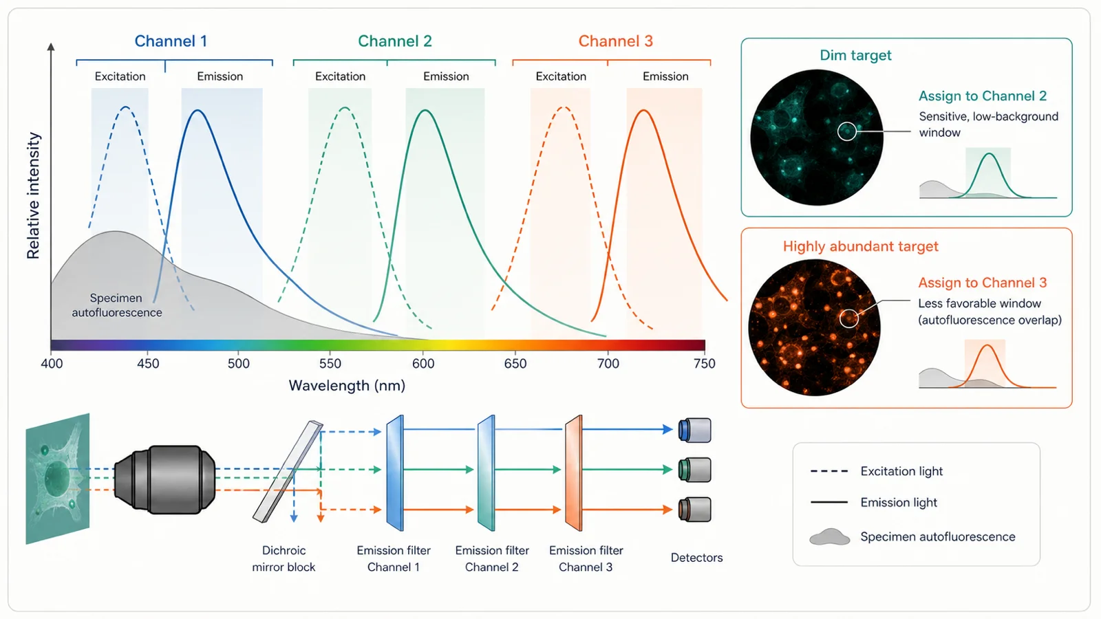
Record the microscope setup before selecting dyes
Record the actual optical path used for the experiment. Dye names and peak wavelengths alone are insufficient because excitation and emission occur across bands, while filters and detectors accept only part of those bands.
| Instrument element | Question | Record |
|---|---|---|
| Excitation source | Which laser lines, LEDs, lamps, or excitation filters are available, and how efficiently do they excite each candidate fluorophore? | Nominal wavelength or band, power control, illumination mode, and any channel-specific attenuation. |
| Dichroic or beamsplitter | Which excitation and emission wavelengths are reflected or transmitted? | Part number or optical configuration and the channels that share the component. |
| Emission filter or detector window | How much intended emission is collected, and how much neighboring emission enters the same channel? | Bandpass limits, long-pass cut-on, spectral detector range, and any adjustable window. |
| Detector | Does sensitivity vary across wavelength, gain, readout mode, or detector type? | Camera or detector model, gain or voltage, binning, readout mode, and channel-specific settings. |
| Objective and optics | Do transmission, numerical aperture, immersion medium, and chromatic performance differ across channels? | Objective model, magnification, numerical aperture, immersion medium, and relevant correction settings. |
| Acquisition mode | Can channels be acquired sequentially, simultaneously, by filter switching, or by spectral detection? | Channel order, simultaneous groups, scan mode, dwell or exposure time, and switching sequence. |
Measure specimen background before assigning channels
Acquire an unstained or label-free specimen through every planned channel using the same preparation, objective, optical configuration, and comparable acquisition settings intended for the stained experiment.
| Background source | Why it matters | Check |
|---|---|---|
| Intrinsic cellular or tissue fluorescence | Collagen, elastin, lipofuscin, red blood cells, pigments, metabolites, and other structures can dominate particular channels. | Unstained specimen imaged across all channels and representative tissue regions. |
| Fixation and processing | Aldehyde fixation, FFPE processing, retrieval, and storage can change channel-specific background. | Unstained controls matched for fixation, retrieval, mounting, and storage duration. |
| Substrate and mountant | Plastic, adhesive, coverslip, mounting medium, or barrier reagents may fluoresce or alter transmission. | Blank substrate and mounted unstained specimen under the final optical configuration. |
| Treatment-related fluorescence | Drugs, nanoparticles, reporters, diet, pigments, or experimental treatments may add signal. | Untreated and treated unstained controls. |
| Out-of-focus light or illumination nonuniformity | Widefield haze and field gradients can make one channel appear intrinsically brighter. | Flat-field reference where appropriate, z-position review, and background measured across the field. |
Far-red channels can reduce background in some specimens, but this is not a universal rule. Check both specimen background and detector sensitivity on the actual microscope.
Assign fluorophores to the targets
| Target property | Question | Check |
|---|---|---|
| Expected abundance | Which target is dim after validated staining, not merely described as low abundance? | Unsaturated singleplex images and signal-to-background measurements on the actual specimen. |
| Biological priority | Which marker is essential to the main conclusion and therefore needs the most robust channel? | Predefined primary and secondary endpoints. |
| Spatial distribution | Are markers diffuse, punctate, membrane-bound, nuclear, or densely co-expressed? | Singleplex localization and expected compartment. |
| Co-expression | Will a very bright marker occupy the same cells or structures as a dim marker? | Biological evidence and singleplex images from matching specimens. |
| Labeling method | Is signal produced by a directly conjugated primary, one fluorescent secondary per primary, amplification, or multiple detection layers? | Labeling stoichiometry, degree of labeling when known, and complete reagent setup. |
| Quantitative requirement | Must intensity be compared across groups, or is the channel used only for identification or segmentation? | Analysis plan, dynamic range, saturation rule, and batch design. |
Assigning the weakest target to the “brightest dye” is only a starting idea. The best channel is the one that gives useful target-dependent signal relative to background while remaining separable from the other markers.
Check spectral overlap in both directions
Two channels can interfere because one excitation source excites both fluorophores, because one fluorophore emits into both detection windows, or because a bright channel saturates and contaminates a neighboring detector.
| Risk | How it happens | Check |
|---|---|---|
| Cross-excitation | The excitation line or filter substantially excites more than one fluorophore. | Acquire each single-color specimen under every excitation and detection channel. |
| Emission bleed-through | A fluorophore emits within the neighboring channel’s filter or detector window. | Inspect raw single-color images in all channels below saturation. |
| Bright-to-dim contamination | A highly abundant marker contributes a small fraction of signal to the channel assigned to a weak marker. | Use single-color controls with labeling density and exposure comparable to the final panel. |
| Detector or display saturation | Clipped pixels hide dynamic range and can exaggerate apparent overlap. | Inspect raw values, saturation indicators, and the brightest expected specimen. |
| Chromatic displacement | Different wavelengths focus or register at slightly different positions. | Use an appropriate multicolor registration reference when the claim depends on subcellular overlap. |
| Spectral-unmixing error | Reference spectra do not match the fluorophore, specimen background, or acquisition configuration. | Use matched single-color and autofluorescence references and inspect residuals or reconstruction artifacts. |
Sequential acquisition can reduce some cross-excitation and emission contamination by acquiring one channel at a time. It cannot make fundamentally overlapping fluorophores independent, remove specimen autofluorescence, or replace single-color controls.
Brightness and photostability depend on the full imaging setup
Intrinsic fluorophore properties
Extinction coefficient, quantum yield, spectral bandwidth, environmental sensitivity, and photochemical stability contribute to potential performance.
Excitation efficiency
A nominally bright fluorophore may perform poorly when the available excitation line is far from its useful absorption range or illumination power is limited.
Detection efficiency
Filter transmission, detector sensitivity, optics, background, and emission-window width determine how much useful signal reaches the image.
Labeling density
Signal depends on antibody occupancy, secondary amplification, conjugation, steric access, and the number of fluorophores attached—not the dye alone.
Supplier brightness rankings are useful for screening, but they are not direct measurements of the final immunofluorescence assay. Compare candidate channels using matched singleplex samples and the actual instrument.
Plan for photobleaching
- Minimize unnecessary illumination during focusing, field selection, and setup.
- Use the lowest excitation and shortest exposure that provide the required signal-to-background and spatial information.
- Record acquisition order because earlier channels receive different illumination histories from later channels.
- Test order effects when repeated scans, z-stacks, tiling, deconvolution input, or long acquisitions are required.
- Keep mounting medium, curing, storage, and time to imaging consistent across quantitative comparison groups.
Required fluorophore and channel controls
| Control | What it checks | What failure looks like |
|---|---|---|
| Unstained specimen | What specimen and preparation background exists in every planned channel? | A channel is assigned to a weak target even though unstained background already occupies most of its useful range. |
| One single-color specimen per fluorophore | How much does this fluorophore contribute to every other acquisition channel? | Signal appears in a channel that contains no corresponding fluorophore. |
| Singleplex reference per marker | Does the marker retain its expected distribution and signal-to-background after multiplex assembly? | The multiplex pattern differs materially from the same marker stained alone. |
| Known-positive and target-negative material | Is the channel detecting target-dependent signal rather than only optical separation? | A spectrally clean channel still shows a target-independent pattern. |
| Method-matched omission control | Does the fluorescent secondary, direct conjugate, amplification layer, or sequential step create signal without the intended target reagent? | Background persists after the relevant primary or detection step is omitted. |
| Registration reference when required | Are channel positions aligned closely enough for the spatial claim? | Apparent subcellular overlap changes after chromatic correction. |
| Photobleaching or order check | Does repeated illumination change later measurements? | Signal depends systematically on acquisition order or scan count. |
See the controls guide and Multiplex IF design guide for antibody-specificity and panel-validation requirements.
Set the acquisition plan before finalizing the panel
- Acquire the unstained specimen first. Establish channel-specific background with the final objective and optical configuration.
- Acquire every single-color control through every channel. Use exposures representative of the final panel rather than a minimal demonstration exposure.
- Identify the brightest expected specimen. Set a range that avoids saturation while retaining the dim target above background.
- Choose sequential or simultaneous groups deliberately. Separate channels with meaningful excitation or emission interaction; preserve speed only where simultaneous acquisition remains valid.
- Define acquisition order. Consider photobleaching, repeated excitation of shared wavelength ranges, and whether field selection pre-exposes the specimen.
- Preserve compatible settings for quantitative comparisons. Record exposure, gain, illumination, detector mode, binning, z-step, and processing rules.
- Save raw individual channels. Preserve data before background subtraction, flat-field correction, deconvolution, spectral unmixing, denoising, thresholding, or display adjustment.
- Inspect channels individually before merging. A visually pleasing composite does not reveal saturation, bleed-through, background, or failed singleplex concordance.
Compare two fluorophore assignments when needed
When two targets compete for the most favorable channels, swap the assignments while keeping the specimen preparation, antibodies, and imaging session constant.
| Variable | Assignment A | Assignment B | Keep constant |
|---|---|---|---|
| Target-to-fluorophore mapping | Target 1 in channel X; Target 2 in channel Y | Swap the two fluorophore assignments when compatible conjugates or detection reagents are available | Specimen, fixation, retrieval or permeabilization, antibody clone and concentration, labeling method, wash, mountant, and imaging session |
| Controls | Unstained, both single-color controls, both singleplex references, positive and target-negative material | Acquire all channels below saturation using the same evaluation rule | |
| Evaluation | Target-dependent signal-to-background, contamination into the other channel, morphology, reproducibility, and dynamic range | Do not select from merged appearance alone | |
Choose the assignment that keeps both markers interpretable. Improving one channel while making the other unusable does not improve the panel.
Before using the fluorophore assignment
- Every fluorophore is efficiently excited and detected by the documented instrument configuration
- Unstained background leaves sufficient usable dynamic range for the assigned target
- Every single-color control shows acceptable contamination across all other channels
- Each marker retains a target-dependent distribution compatible with its validated singleplex reference
- No required channel is saturated in the brightest expected specimen
- Acquisition order and illumination history do not create a material bias
- Channel registration is adequate for the spatial scale of the biological claim
- The panel is reproducible across the required specimens, staining batches, days, operators, and instruments
- Raw individual channels, metadata, controls, and processing steps are retained
Recognize channel- and fluorophore-related artifacts
| Observation | Possible explanation | Check |
|---|---|---|
| A dim channel becomes visible only at extreme exposure | Poor excitation, weak detector response, low labeling density, high specimen background, or failed staining | Known-positive singleplex, instrument map, unstained background, and an alternate compatible channel |
| A structure appears identically in two channels | Bleed-through, cross-excitation, autofluorescence, or true co-expression | Both single-color controls, unstained specimen, target-negative material, and individual raw channels |
| The dim marker appears only near very bright structures | Bright-to-dim spectral contamination or local saturation | Single-color control matched for brightness, lower exposure, narrower detector window, or alternate assignment |
| Signal fades across a z-stack or tile scan | Photobleaching, cumulative illumination, or order-dependent acquisition | Reverse channel or field order, reduce illumination, and compare first versus last frames |
| One image corner is brighter in several channels | Illumination nonuniformity, shading, coverslip geometry, or sample thickness | Flat-field or reference slide, rotate the specimen, and inspect whether the pattern follows the field or biology |
| Colocalization shifts between channels | Chromatic misregistration, focus offset, z-position mismatch, or sequential motion | Multicolor registration reference, channel-specific focus, and acquisition timing |
| Spectral unmixing creates negative halos or unexpected structures | Mismatched reference spectra, saturation, insufficient spectral sampling, or unmodeled autofluorescence | Matched single-color references, raw spectral data, residual inspection, and an autofluorescence reference |
Common fluorophore-selection mistakes
| Mistake | Why it fails | Better approach |
|---|---|---|
| “The emission peaks are far apart, so the channels cannot bleed.” | Full spectra, excitation bands, detector windows, labeling density, and saturation determine contamination. | Acquire every single-color control through every final channel. |
| “The far-red dye is always best for the dimmest target.” | Detector sensitivity, excitation efficiency, optics, and specimen background vary by instrument and sample. | Measure target-dependent signal-to-background on the actual system. |
| “The supplier’s brightest dye will give the brightest image.” | Actual signal also depends on excitation, detection, labeling density, antibody performance, mountant, and specimen environment. | Compare matched singleplex samples using the final microscope. |
| “Sequential scanning eliminates all crosstalk.” | Sequential acquisition does not remove overlapping emission, autofluorescence, saturation, or invalid references. | Use compatible fluorophores and single-color controls first. |
| “Changing exposure separately for each group improves presentation.” | It can create apparent biological differences and destroys direct intensity comparability. | Use a predefined unsaturated acquisition rule and disclose any non-comparable display scaling. |
| “A merged image proves colocalization.” | Display colors can hide bleed-through, registration error, out-of-focus light, and segmentation mistakes. | Inspect raw channels, controls, registration, z-position, and an analysis method matched to the claim. |
| “A panel that worked once is validated permanently.” | Clone, lot, conjugate, fluorophore, optical configuration, specimen, retrieval, and analysis changes can alter the panel. | Define revalidation triggers and retain a stable batch reference. |
What to record for fluorophore selection
- Biological question, required markers, expected compartments, abundance, co-expression, and unit of interpretation
- Primary and detection reagents, clone, lot, host, conjugation or secondary method, fluorophore, and degree of labeling when available
- Microscope, illumination source, excitation lines or filters, dichroics, emission filters or detector windows, detector, objective, and acquisition mode
- Unstained background in every channel and specimen regions used to measure it
- Single-color controls, singleplex references, positive and target-negative material, omission controls, and registration references
- Target-to-fluorophore assignment rationale and alternate assignments tested
- Channel order, simultaneous or sequential groups, exposure, gain, illumination, dwell time, averaging, binning, z-step, and saturation rule
- Mounting medium, curing, storage, light exposure, time to imaging, and photobleaching or order checks
- Bleed-through, cross-excitation, registration, background, dynamic range, morphology, and repeatability results
- Raw-file location, processing, unmixing references, display adjustments, rejected assignments, acceptance decision, and revalidation triggers
References and protocol sources
- Selecting optical filters for fluorescence microscopy Technical guide
Thermo Fisher Scientific, Molecular Probes Handbook
Excitation filters, dichroic beamsplitters, emission filters, spectral separation, autofluorescence rejection, and instrument-aware optical trade-offs.
- Guide for using the Fluorescence SpectraViewer Technical guide
Thermo Fisher Scientific
Instrument-aware fluorophore compatibility and quantitative inspection of spectral overlap.
- Bleed-through in fluorescence imaging Technical guide
Thermo Fisher Scientific
Recognition of signal from one fluorophore in a neighboring channel and mitigation through compatible fluorophore and filter selection.
- Multiplexed IHC staining with primary antibodies conjugated to fluorophores Manufacturer protocol
Thermo Fisher Scientific
Directly conjugated primary-antibody workflow, single-color controls, negative controls, coverage, and antibody titration.
- The Society for Immunotherapy of Cancer statement on best practices for multiplex immunohistochemistry and immunofluorescence staining and validation Consensus guideline
Janis M. Taube and colleagues . Journal for ImmunoTherapy of Cancer (2020) . DOI: 10.1136/jitc-2019-000155
Singleplex-first panel development, marker-level controls, multiplex-to-singleplex concordance, and revalidation after panel changes.
- Society for Immunotherapy of Cancer: updates and best practices for multiplex immunohistochemistry and immunofluorescence image analysis and data sharing Consensus guideline
Janis M. Taube and colleagues . Journal for ImmunoTherapy of Cancer (2025) . DOI: 10.1136/jitc-2024-008875
Acquisition, segmentation, phenotyping, quality control, batch correction, and sharing of raw and processed outputs.
- Society for Immunotherapy of Cancer: Standards for Reporting of Multiplex Immunohistochemistry/Immunofluorescence Assays (STORMI) Consensus guideline
Sam Sater and colleagues . Journal for ImmunoTherapy of Cancer (2025) . DOI: 10.1136/jitc-2025-012280
Minimum reporting elements for panel design, staining controls, acquisition, analysis, and reproducibility.